Application Note, Custom Engineered Motion Systems, Electronics, Motion Control Platforms, Precision Manufacturing
Application Note
Advanced Motion Control Optimizes Mechanical Micro-Drilling
In micro-drilling process equipment, the most popular ways to create microvias (blind or buried vias with a diameter ≤150 µm) are mechanical drilling and laser drilling. Mechanical drilling is mainly used in larger apertures such as PCBs or IC substrates. Laser drilling is mainly used in finer apertures such as silicon wafers, ceramic substrates and sapphire substrates. Although many of the requirements of mechanical and laser drilling are identical, this discussion will focus on how advanced motion control technology plays a critical role in the success of mechanical-drilling process equipment. Mechanical drilling machines, especially the six-spindle PCB driller, are still the most widely used PCB drillers in this market. We will discuss the main challenges and the technology being used in this type of machine.
Lots of Point-to-Point Moves
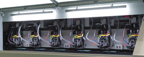
Mechanical PCB drilling machines require the servo systems to move the spindle and the substrate (PCB) to the target drilling locations as quickly as possible. Figure 1 is a traditional six-spindle PCB driller with a split-bridge design. The bottom axis moves the substrate, and the top axis moves the spindles. The most common challenges in this application are: (1) ensuring the XY servo stages are “tuned” to be fast, stable and accurate; (2) reducing friction effects because most of these machines are ball-screw-driven; (3) having a comprehensive software library, which is required for machine makers to design the software interface that meets the end-user requirements.
Tuning Servo Stages
Part dimensions, mass and the dynamic performance requirement will all influence the difficulty of XY servo stage system tuning. Normally PCB substrates are larger than 500 x 500 mm, and because of the tight throughput requirements from the PCB drilling machine, the tuning of the servo stages could be a very challenging task. The main reason is the pursuit of the shortest “move-and-settle time” – the time for a stage system to move from point A to point B and settle within a certain threshold.
Normally a motion system control will provide an autotuning routine (Figure 2), or a “step response” tuning technique that is mainly done in the Time Domain. This type of tuning process could be effective in easier applications. However, because Time Domain tuning techniques cannot estimate the resonance, estimate the pole zero map or set up the filters, many times the user has to reduce the servo gains to avoid system oscillation. Unfortunately, reducing the gains often also means degrading throughput and process yield.
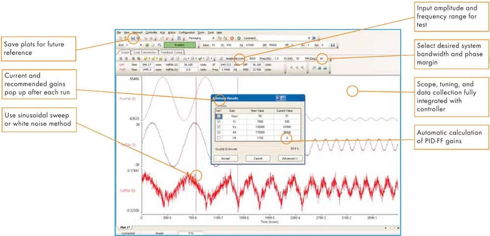
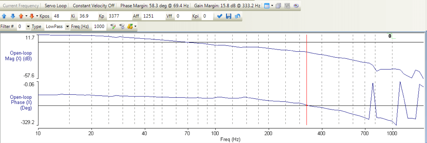
Using frequency domain techniques (frequency response analysis) is a more advanced tuning approach and will yield better throughput. The frequency response analysis technique injects a sinusoidal signal from low to high frequency into the motor and captures the phase and gains at each frequency. The phase margin and gain margin are then evaluated in order to make adjustments to the servo gains. High performance motion controllers like the Aerotech Automation 3200 can easily shape the loop, adjust the Bode plot graphically, set up the servo filters and ultimately increase the gains to maximize the throughput (Figure 3).
Reducing Friction Effects
The PCB drilling machine market is very competitive in both price and performance. For these reasons, the most common PCB mechanical drilling machine designs use ball-screw-driven stages. It is very cost-effective for a ball-screw system to move the large substrate and provide good positioning accuracy (for this market). However, due to the large screw pitch, the friction will limit the low frequency gain of the axis, which means the move-and-settle time and the directional reversal time will be longer than desired. Traditionally, machine builders tried to increase the servo loop gains universally so the friction effect is reduced. Unfortunately, that will also increase the possibility of system instability.
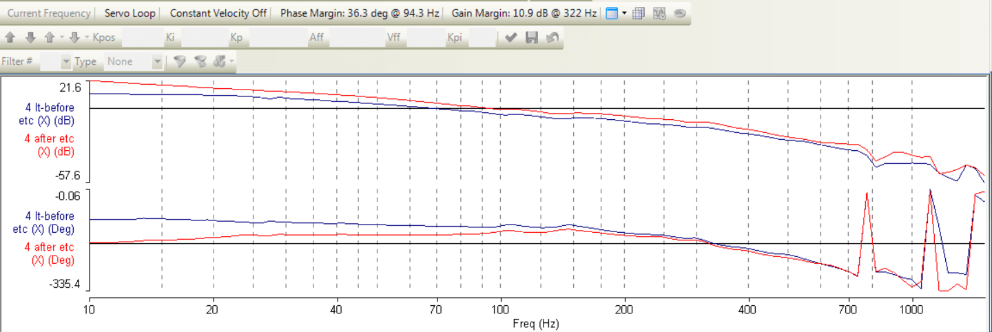
In order to have a stable, high-bandwidth system, Aerotech developed a control technique called Enhanced Tracking Control (ETC). Bearing friction creates a diminished response at low frequencies, and lower loop gain means a slower response to disturbances. The Enhanced Tracking Control algorithm boosts low frequency response of servo mechanisms leading to dynamic behavior much closer to an ideal frictionless system. With the implementation of ETC, a PCB drilling machine’s move and settle time performance is improved significantly.
Flexible Software Library
Most PCB drilling machine users expect the system to be plug-and-play, which means the software interface is critical to the success of the system. Aerotech provides comprehensive software libraries that are required for software designers to flexibly design the software interface, data analysis, operation workflow, safety, IO and more. G-code and M-code support is a “must have” for a PCB drilling machine, as the software designers commonly convert the PCB drawings into G-code to operate and graphically display the drilling trajectories. Aerotech’s C# and C libraries, already being used in commercial PCB drilling machines, can provide the required functionalities for all of the motion requirements.
Advanced motion controllers have many special features that allow the large quantity of aperture coordinates to be processed at the highest possible efficiency. For example, Aerotech’s Look Ahead feature can determine the trajectory of upcoming apertures. The Queue mode allows the data to be processed in the First-In, First-Out fashion and therefore the embedded memory size does not restrict how many points the user can actually process.
An additional control technique for improving process efficiency is velocity profiling. The throughput requirements of PCB drilling machines are extremely high; there will be no time for waiting in-between moves. Two features from Aerotech motion controllers are used to deal with this issue: Wait Mode Auto and Velocity Profiling. The WAIT MODE AUTO command configures the controller to wait the minimum quantity of time between moves in order to decrease the cycle time of a program. Wait modes apply to the end of a velocity profiled sequence and not to commands within the sequence. VELOCITY PROFILING is used to blend multiple coordinated motion commands into one continuous motion path. In velocity profiling mode, the controller does not decelerate to zero between consecutive coordinated moves.
Example
The following example demonstrates the process of optimizing a mechanical PCB micro-drilling system. Here the servo stages make five moves with a 25.4 mm stroke per move.
Motion parameters are:
Stroke: 25.4 mm
Velocity: 415 mm/s
Acceleration: 10,680 mm/s2
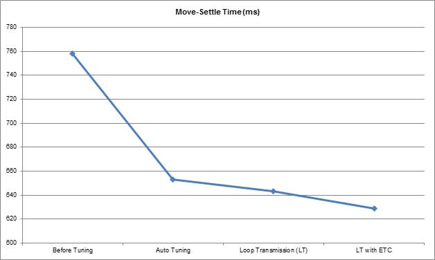
The Wait Mode Auto feature will be activated, and the In Position Threshold is set at 2 µm. This example will show the results using different tuning techniques and tools including AutoTune, Loop Transmission and ETC. Move-and-settle time performance is measured with Aerotech’s Digital Scope tool.
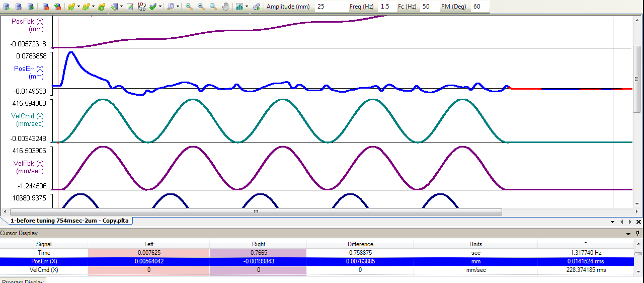
As shown in Figure 6, before tuning the largest following error is at the accel/decel zone and is 78 µm to -14 µm. The move time is 615 ms, and the settling time is 143 ms. The move and settle time combined is 758 ms to the target settling threshold (2 µm).
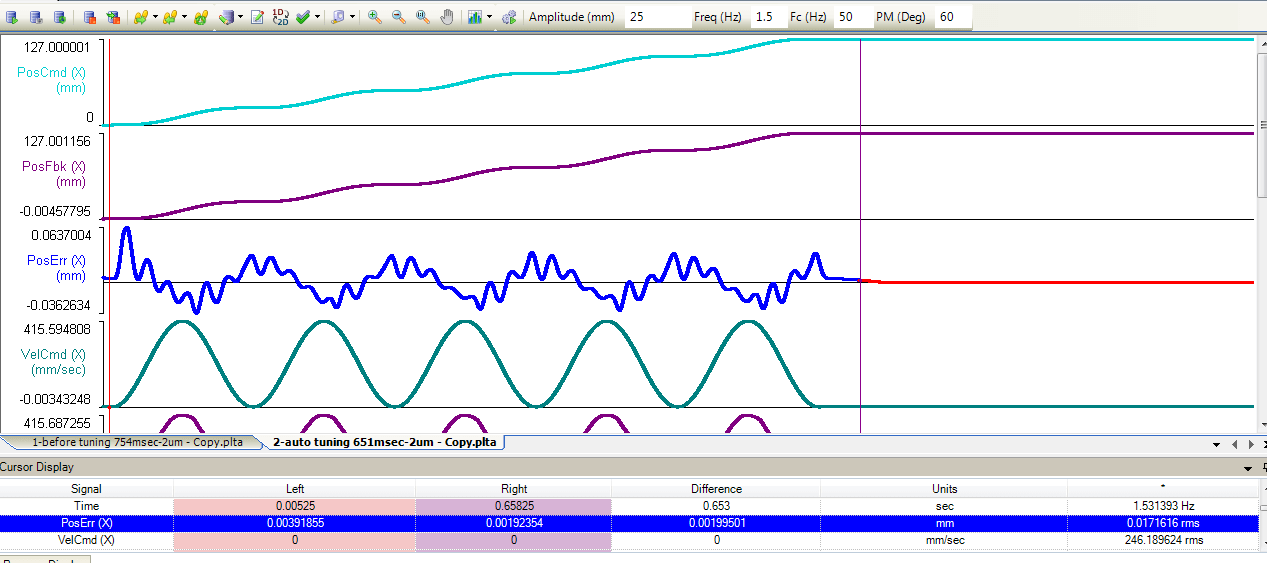
The second example tunes the system using the AutoTune tool. AutoTune increases the servo loop gain from Kp = 3377; Ki=36.9; Kpos = 48 to Kp = 2320; Ki = 71; Kpos = 126. From Figure 7, the largest following error is now from 63 µm to -36 µm, the move time is 615 ms and the settling time is 38 ms. The AutoTuning technique reduced the cycle time to 653 ms.
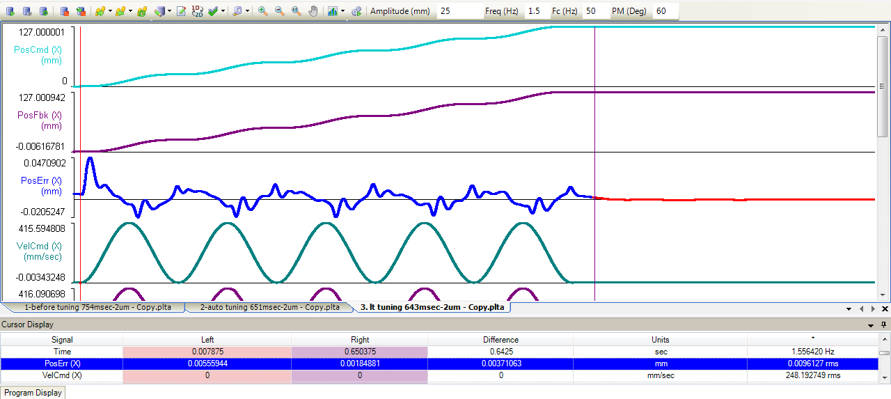
The next step is to apply the Loop Transmission tool. We excite the system with a sinusoidal signal from low to high frequency and capture the phase and gains at each frequency. We will optimize the system performance directly from the Bode Plot.

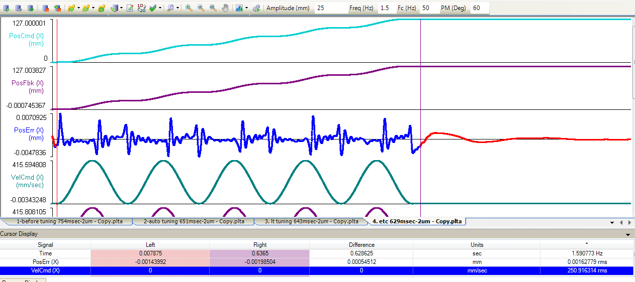
To further optimize the move-and-settle performance, we apply the ETC algorithm. With the low frequency boost, we are able to further reduce the move and settle time and even the tracking error and acceleration/deceleration is improved. As shown in Figure 11, this further reduced the cycle time to 629 ms.
Conclusion
Advanced motion control techniques can significantly improve the throughput and quality of high-performance mechanical PCB micro-drilling. From fundamental servo tuning using frequency response tuning techniques, filtering the resonance and increasing the servo gains to improve the throughput to reducing the friction effect by boosting low frequency response and improving program execution efficiency in order to quickly process bulk data points, there are a variety of control methods that can help you reach your goals.